Two degree-of-freedom system bath model
Introduction
Locating the Dividing Surface (DS) in chemical reactions has been the focus of many rate constant calculations both for reactions in solution and in vacuum thanks to the Transition State Theory; a classical theory developed by Wigner, Eyring, Gwynne Evans and Polanyi;[1], [2], [3], [4] that calculates the rate of the reaction as the equilibrium flux of reactive trajectories through that DS.
In this chapter, we take a different point of view on the two supposed assumptions of TST (REFER TO TST SECTION). By treating the locally non-recrossing criterion for the dividing surface as an approximation, one is implying that there exists some other criterion of higher priority for locating the TS. However, in our view the location of the TS is defined solely by the satisfaction of the locally non-recrossing criterion. Hence, if one finds a putative TS whose associated dividing surface suffers recrossing (leading to a reduction in the TST transmission coefficient), then the TS is, strictly speaking, in the wrong place. It has been argued that there can be circumstances in which no dividing surface exists that would satisfy the locally non-recrossing criterion. However, this argument is based on reactive and recrossing trajectories passing through a common point. That is possible only in configuration space, because every point in phase space is unique. The original definition of the dividing surface used by Wigner was in phase space, and that is the definition we adopt here.[5] That said, there may be no problem with using such an approximate TS, as done by Grote Hynes Theory, for the computation of the overall rate constant of a single-step reaction [6], [7], [8], [9]. However, as discussed in [10], not every effect can be explained with configuration-space models. One of these effects, which we have called the inertial barrier, arises when changes in shape of a reacting solute are resisted by the solvent because of a timescale mismatch between the solute dynamics (typically ~100 fs for transit from a PES saddle point to the next local minimum, in vacuo) and solvent dynamics (typically 1 - 10 ps, and sometimes much longer, for relocation of solvent molecules in the first shell around the reacting solute) [11], [12], [13], [14], [15], [16], [17], [18], [19] Another potential problem arises, for example, when one is concerned with branching to several products after a rate-determining TS. The supposed equilibrium assumption of TST is not really an assumption either, because it can be shown to be a consequence of the locally non-recrossing requirement [20]. Of course, finding the exact DS is not an easy task for reactions of polyatomic molecules and could even be technically impossible for reactions in solutions.
However, the construction of the DS for 2 DoF systems using the Lyapunov family of unstable POs was presented in a series of papers by Pollak, Pechukas, and Child in the late 1970's to early 1980's.[21], [22], [23], [24], [25] The resulting Periodic Orbit Dividing Surface (PODS) is a hypersurface in phase space arising from the unstable PO. It has been shown to have the required no-recrossing properties described above. Of particular interest was the recognition that as the total energy of trajectories increased, the location of the PODS would change, and that, in general, its projection onto the PES did not need to pass through the index one saddle point that is considered to be the location of the Transition Structure in many chemical models. In the present chapter, we emphasize that it is not only energy which can cause the PODS to move, but at least in some models, its location may also be mass dependent. This feature is of particular relevance to the solvent-derived inertial barrier mentioned above.
(WRITE THE OBJECTIVE OT THE CHAPTER)
Development of the Problem
(INTRODUCING THE MODEL)
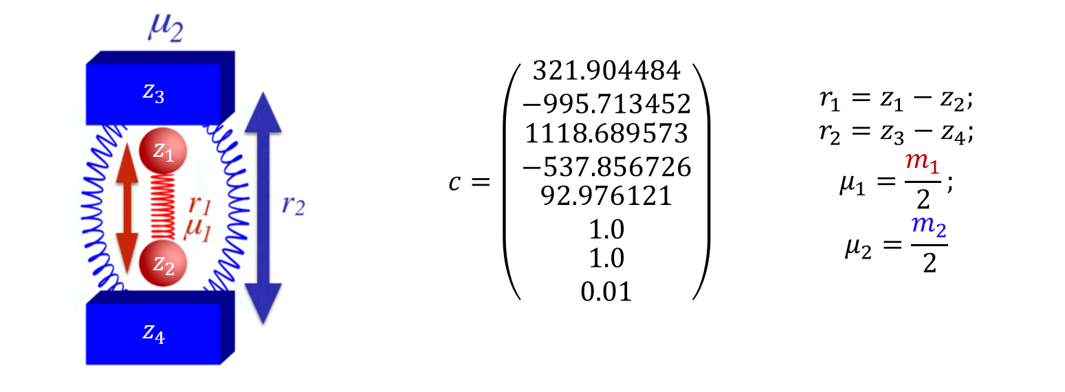
Our model potential (see fig:1) consists of a one-dimensional double well oscillator that represents the reactive system, coupled to a one-dimensional harmonic oscillator representing the bath. The only coupling between the two oscillators is a Lennard-Jones-like repulsion potential term. Consequently, this model is appropriate only for nonpolar systems; our concern here is the consequence of non-bonded interactions between solvent and solute, not the more commonly studied polar interactions.

The Hamiltonian that describes the system is as follows:
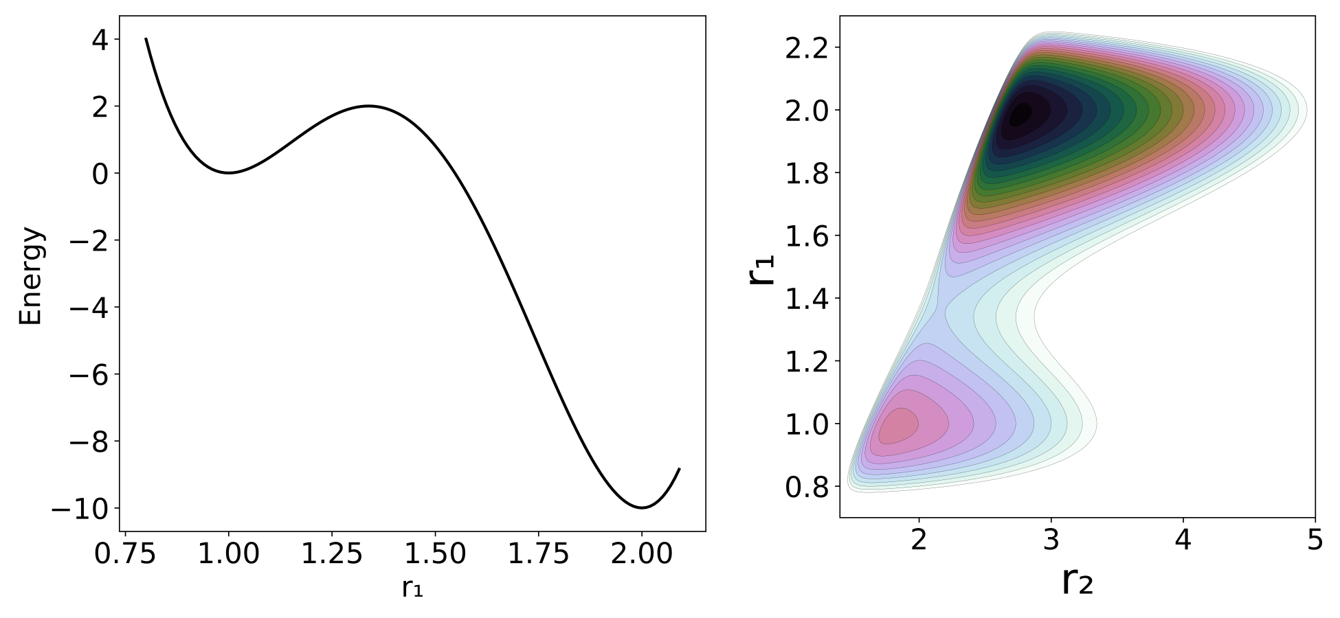
\begin{equation} H(\mathbf{x})=H(\mathbf{r},\mathbf{p})=\frac{p_1^2}{2\mu_1}+\frac{p_2^2}{2\mu_2}+\sum_{j=1}^{5} c_j r_1^{j-1}+c_6 (c_7-r_2 )^2+\frac{c_8}{(r_2-r_1 )^{12}} \label{modelEq} \end{equation}where the subscripts 1 and 2 refer to the reactive system and bath oscillators respectively; $r=(r_1,r_2 )$ is the position of the two oscillators and $p=(p_1,p_2 )$ represents the conjugate momenta. The reduced mass of each oscillator is represented by $\mu$, and c are coefficients whose values are listed in fig:1. The potential energy can be divided between $V_1 = \sum_{j=1}^{5} c_j r_1^{j-1}$ as the potential of the reactive system, $V_2=c_6 (c_7-r_2 )^2$ as the potential of the bath and $V_{int}=c_8/(r_2-r_1 )^{-12}$ as the interaction between the two; hence $V=V_1+V_2+V_{int}$. The potential of the reactant, shown in fig:2, is chosen to have a minimum at $r_1=1.0$ and a second one at $r_1=2.0$ , with respective potential energies $V_1=0.0$ and $V_1=-10$. The maximum energy is at $r_1=1.33867$ and $V_1=2.0$. The full potential, shown in fig:2, has a saddle point at $r_1=1.36561$ and $r_2=2.161769$ at $V=3.47291$. The "reactant" minimum occurs at $r_1 = 0.98779$, $r_2 = 1.80661$, $V = 0.77040$. The "product" minimum occurs at $r_1 = 1.98517$, $r_2 = 2.75642$, $V = -6.66284$.

Revealing the Phase Space Structures
One of the reasons for choosing this system is that periodic orbits that define the PODSs can be computed easily. All the calculations were carried out at an energy of $3.691966889$ which is slightly above the energy of the saddle point.
In order to understand the properties of the trajectories that depart from the DS we need to sample its points in phase space. The procedure, applicable to a 2 DoF Hamiltonian system, selects points on a 2D surface with fixed total energy (E), where the periodic orbit forms the one dimensional boundary of the DS. The algorithm is as described in [26], [27]:
- Locate an unstable PO.
- Project the unstable PO into configuration space, which gives a curve in configuration space.
- Choose points on the curve $(x_i,y_i)$ for $i=1,...,N$, where N is the desired number of points. The points are spaced uniformly according to distance along the PO.
For each point $(x_i,y_i )$ determine $p_{x_{max},i}$ by solving for $p_x$.
\begin{equation} H(x_i,y_i,p_x,0)=\frac{p_x^2}{2\mu_x}+V(x_i,y_i)=E \label{PODSsampEq} \end{equation}
Note that the solution of this equation requires $E- V(x_i,y_i ) \ge 0$, and there will be two solutions, $\pm p_{x_{max},i}$.
- For each point $(x_i,y_i)$ choose points $p_{x_j}$ for $j=1,...,K$, with $p_{x_1}=-p_{x_{max},i}$ and $p_{x_K}=p_{x_{max},i}$ and solve the equation $H(x_i,y_i,p_x,p_y)=E$ to obtain $p_y$.
The geometrical structure of the DS sampled in this manner is a one parameter family of circles. The parameter defining the family is given by the distance along the projection of the PO onto the configuration space from Steps 1-3 in the algorithm above, and the momentum-space circles are given by the following equation obtained from the Hamiltonian:
\begin{equation} \frac{p_x^2}{2\mu_x}+\frac{p_y^2}{2\mu_y}=E-V(x_i,y_i) \label{DSGeomEq} \end{equation}Implications for Reaction Dynamics
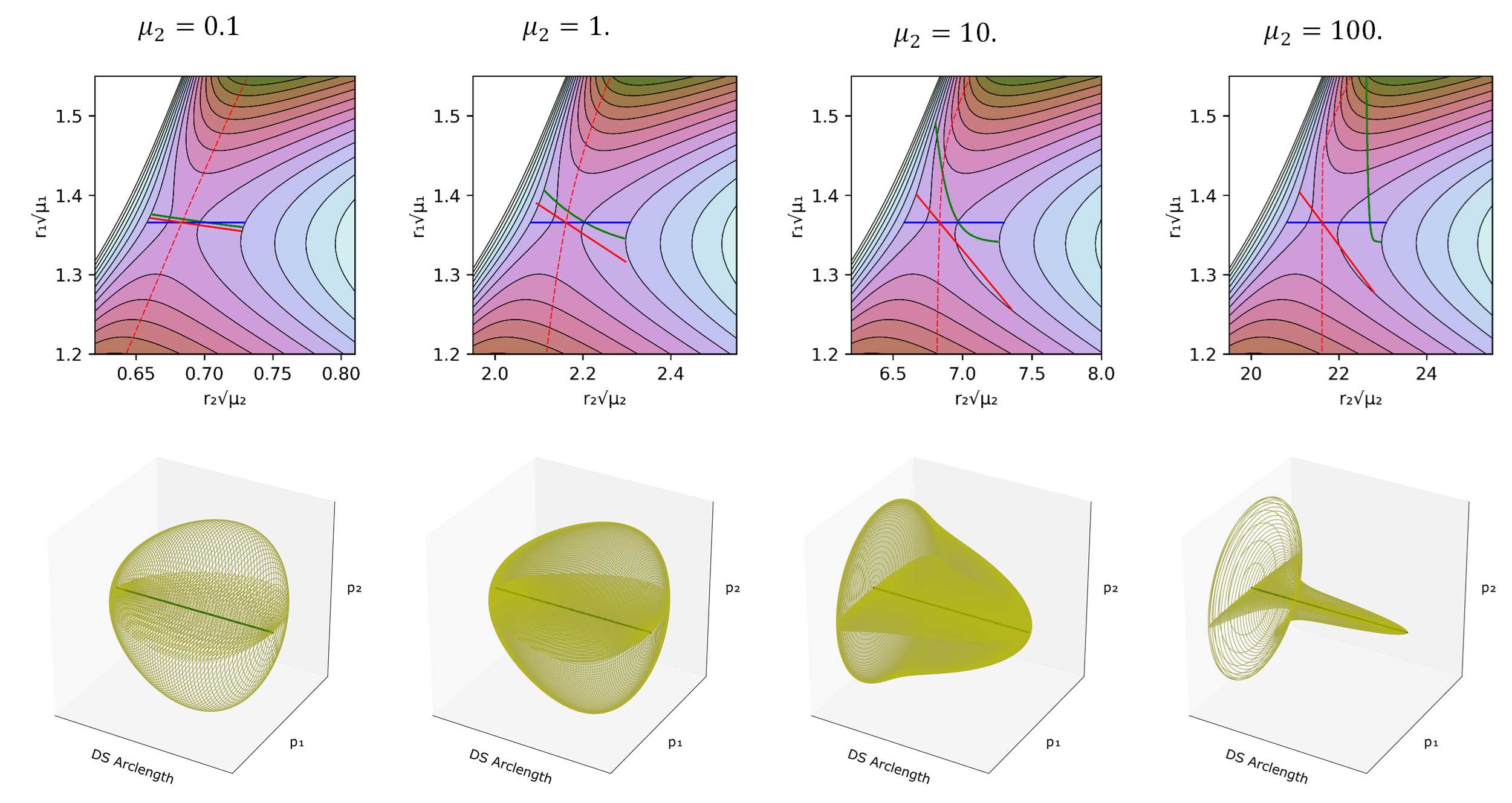
In fig:3 (top) we can see the projection of the calculated PODSs in configuration space. fig:3 also includes two approximations to the DS explained in the caption and shows how the three of them respond as $\mu_2$ changes. The geometry of this one parameter family of circles depends on the nature of the projection of the PO into configuration space. In this particular case the PO projections are arcs where a configuration space point on the projection of the PO moves back and forth along the arc. This means that the endpoints of the arc are turning points with $p_x=p_y=0$, where the circles defined by eq. \ref{DSGeomEq} shrink to points. This implies that the geometry of the one parameter family of circles defines a 2D sphere (see fig:3 bottom).

Effect of Solvent's Mass
It can be seen that, for low reduced masses, the approximate DSs are close to the PODS. That is because the bath can rapidly adapt to the position of the reactive system. However, as $\mu_2$ increases the PODS starts to curve and to displace from the approximate DSs, moving closer to the product well.
What the model reveals in fig:3 is that when $\mu_2$ is small with respect to $\mu_1$, the projections of the three dividing surfaces are quite close to each other, but as the relative reduced mass of the solvent model gets larger, the true dividing surface moves away from the ones that are rooted at the PES saddle point. The important point here is that, even if one could take the solvent into account properly in defining an IRC for a solution-phase reaction (which generally one cannot), a DS orthogonal to that IRC but still centered on the PES saddle point (the red line) would be incorrect.
But how can we be sure that these PODS are in fact the no-recrossing DS? From the sampled trajectories we can measure the time taken to reach a determined region (transit time), in this case the PES minimum identified as the product well. Then we can perform the same calculation but with trajectories starting on the DS defined only with $r_1$ (the blue line in fig:3). The blue line corresponds to the common choice for solution phase reactions of assigning the transition state location to the PES saddle point, and assuming that the reaction coordinate is entirely determined by the solute. fig:4 is a representation in phase space of the transit times of trajectories that start on the true and approximate dividing surfaces with different initial $p_\perp$, the momentum normal to the dividing surface. The transit times (calculated as the time for $r_1$ to reach a value greater than that for product minimum) show brighter colors in Figure fig:4 as the transit time increases. The expected results for a DS is that trajectories starting with negative momenta normal to the dividing surface ($p_\perp<0$), i.e. directed to the reactant well, would take longer to reach the product well than those that start with positive momenta. This is clearly the case for the PODS as can be seen in Figure 6, where $p_\perp=0$ (which corresponds to the PO) provides an exact line of demarcation in the transit times. By contrast, the approximate DS shows long and short transit times on both sides of $p_1=0$. It is interesting to note that those areas where the transit times are long for $p_1>0$ or short for $p_1<0$ correspond to recrossing of trajectories, and that the amount of recrossing gets larger as $\mu_2$ increases. Thus, the approximate DS becomes a poorer and poorer choice for the transition state as the mass of the bath oscillator increases.
) and (Bottom) the DS conventional definition of the TS (blue DS in [fig:3](#DSCloseFig)). The color scale goes from dark colors for short times to brighter colors for long times. The quantity $p_\perp$ is the momentum perpendicular to the dividing surface, with a positive sign being in the direction of the product.](Figures\TransitT.png)
The brighter colored bands visible on the reactant sides ($p_\perp <0$) in Figure fig:4 are associated with the many periodic orbits located in the reactant well. Trajectories that approach these POs can spend a long time before finally crossing over to the product well.
References
- H. Pelzer and E. Wigner, “The speed constansts of the exchange reactions,” Z. Phys. Chem. B., vol. 15, p. 445, 1932.
- H. Eyring, “The Activated Complex in Chemical Reactions,” J. Chem. Phys., vol. 3, no. 2, pp. 107–115, 1935.
- M. G. Evans and M. Polanyi, “Some applications of the transition state method to the calculation of reaction velocities, especially in solution,” Trans. Far. Soc., vol. 31, no. 0, pp. 875–894, 1935.
- S. Glasstone, K. J. Laidler, and H. Eyring, The theory of rate processes: the kinetics of chemical reactions, viscosity, diffusion and electrochemical phenomena. New York: McGraw-Hill Book Company, inc., 1941.
- R. G. Mullen, J. E. Shea, and B. Peters, “Communication: An Existence Test for Dividing Surfaces Without Recrossing,” J. Chem. Phys., vol. 140, no. 4, p. 041104, 2014.
- R. F. Grote and J. T. Hynes, “The Stable States Picture of Chemical Reactions. II. Rate Constants for Condensed and Gas Phase Reaction Models,” J. Chem. Phys., vol. 73, no. 6, pp. 2715–2732, 1980.
- J. T. Hynes, “Crossing the Transition State in Solution,” in Solvent Effects and Chemical Reactivity, O. Tapia and J. Bertrán, Eds. Dordrecht: Springer Netherlands, 2002, pp. 231–258.
- J. T. Hynes, in The theory of chemical reaction dynamics, vol. 4, M. Baer. B. R., Ed. Fla. CRC Press, 1985, p. 171.
- G. van der Zwan and J. T. Hynes, “Dynamical polar solvent effects on solution reactions: A simple continuum model,” J. Chem. Phys., vol. 76, no. 6, pp. 2993–3001, 1982.
- R. Garcia-Meseguer and B. Carpenter, “Re-Evaluating the Transition State for Reactions in Solution,” Eur. J. Org. Chem., vol. 2019, no. 2-3, pp. 254–266, 2018.
- D. L. Bunker and B. S. Jacobson, “Photolytic cage effect. Monte-Carlo experiments,” J. Am. Chem. Soc., vol. 94, no. 6, pp. 1843–1848, 1972.
- M. L. Horng, J. A. Gardecki, A. Papazyan, and M. Maroncelli, “Subpicosecond Measurements of Polar Solvation Dynamics: Coumarin 153 Revisited,” J. Phys. Chem., vol. 99, no. 48, pp. 17311–17337, 1995.
- A. A. Deniz, B. Li, and K. S. Peters, “Role of Polarization Caging in the SN1 Reaction of Diphenylmethyl Chloride: A Picosecond Kinetic Study,” J. Phys. Chem., vol. 99, no. 32, pp. 12209–12213, 1995.
- S. L. Chang and T.-M. Wu, “A possible nonpolar solvation mechanism at an intermediate time scale: the solvent-cage expansion,” Chem. Phys. Lett., vol. 324, no. 5, pp. 381–388, 2000.
- P. Larrégaray, A. Cavina, and M. Chergui, “Ultrafast solvent response upon a change of the solute size in non-polar supercritical fluids,” Chem. Phys., vol. 308, no. 1, pp. 13–25, 2005.
- J. M. Anna and K. J. Kubarych, “Watching solvent friction impede ultrafast barrier crossings: A direct test of Kramers theory,” J. Chem. Phys., vol. 133, no. 17, p. 174506, 2010.
- J. Clark, T. Nelson, S. Tretiak, G. Cirmi, and G. Lanzani, “Femtosecond torsional relaxation,” Nat. Phys., vol. 8, p. 225, 2012.
- S. Thallmair, M. Kowalewski, J. P. P. Zauleck, M. K. Roos, and R. de Vivie-Riedle, “Quantum Dynamics of a Photochemical Bond Cleavage Influenced by the Solvent Environment: A Dynamic Continuum Approach,” J. Phys. Chem. Lett., vol. 5, no. 20, pp. 3480–3485, 2014.
- B. K. Carpenter, J. N. Harvey, and D. R. Glowacki, “Prediction of enhanced solvent-induced enantioselectivity for a ring opening with a bifurcating reaction path,” Phys. Chem. Chem. Phys., vol. 17, no. 13, pp. 8372–8381, 2015.
- J. I. Steinfeld, J. S. Francisco, and W. L. Hase, Chemical kinetics and dynamics. New Jersey: Prentice Hall Englewood Cliffs, 1989.
- P. Pechukas and E. Pollak, “Trapped trajectories at the boundary of reactivity bands in molecular collisions,” J. Chem. Phys., vol. 67, no. 12, pp. 5976–5977, 1977.
- E. Pollak and P. Pechukas, “Transition states, trapped trajectories, and classical bound states embedded in the continuum,” J. Chem. Phys., vol. 69, no. 3, pp. 1218–1226, 1978.
- P. Pechukas and E. Pollak, “Classical transition state theory is exact if the transition state is unique,” J. Chem. Phys., vol. 71, no. 5, pp. 2062–2068, 1979.
- E. Pollak, M. S. Child, and P. Pechukas, “Classical transition state theory: A lower bound to the reaction probability,” J. Chem. Phys., vol. 72, no. 3, pp. 1669–1678, 1980.
- P. Pechukas, “Recent Developments in Transition State Theory,” Ber. Bunsen-Ges. Phys. Chem., vol. 86, no. 5, pp. 372–378, 1982.
- F. A. L. Mauguiere et al., “Phase space barriers and dividing surfaces in the absence of critical points of the potential energy: Application to roaming in ozone,” J. Chem. Phys., vol. 144, no. 5, p. 054107, 2016.
- G. S. Ezra and S. Wiggins, “Sampling Phase Space Dividing Surfaces Constructed from Normally Hyperbolic Invariant Manifolds (NHIMs),” The Journal of Physical Chemistry A, vol. 122, no. 42, pp. 8354–8362, 2018.
